Using ITPFIND
Phil Hurvitz
phurvitz <at> u <dot> washington <dot> edu
Contents
- Overview
- Download
- Uncompress
- Install IDL
- File preparation
- Getting start point locations
- Running ITPFIND
- Running georectification in Imagine
Overview
ITPFIND is an application that will automatically find image reference points for image rectification.
It is written by Robert Kennedy at Oregon State University.
ITPFIND is written to run in IDL.
It creates input and reference X and Y point text files for import to Imagine or other image rectification software.
return to top
Download
To obtain ITPFIND, visit Robert's web page and get the zip file itp_find.zip.
return to top
Uncompress
Once you have downloaded the zip file, uncompress it. The zip file will contain a number of files. Make sure to unzip using directories. You should see a series of files and a few directories (images and paramfiles).
These instructions will make reference to files and directories, it is assumed these are at or below the itp_find level, where things are uncompressed. It should not make a difference where the itp_find directory is located on the file system.
Before working with the application read the instructions (ITPFIND_v2.0_documentation.doc).
return to top
Install IDL
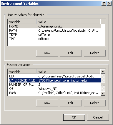
- In order to run ITPFIND, IDL must be installed. If you have installed ENVI, then IDL will be installed. We have a license for IDL and ENVI on one of the CFR servers. To access the license, set up an environment variable:
LM_LICENSE_FILE
1700@license.cfr.washington.edu
- Alter environment variables using Control Panel > System > Advanced > Environment Variables
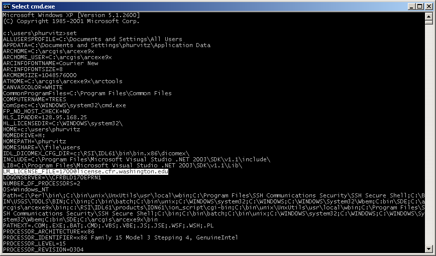
- Verify the variable is set by opening a command prompt and listing variables:
return to top
File preparation
Before ITPFIND can br run, there are a few files that may need to be created and/or modified. These include:
squeet_master.txt (does not necessarily need modification)
This file tells the application where to find the other parameter files (listed directly below). So unless you decide to put files in different places, you do not need to modify this file.
paramfiles\squeet_images.txt
This file contains the relative or absolute pathnames to the files and their properties. I have written an AML that will generate the bare bones of this file (described below). The contents of the file looks something like this:
Filename:                                      images/19970618_p48r26.img
File codename:                                 19970618_p48r26
Start point:(x,y):                             460588.832584, 5350162.848925
Pixel center to pixel center distance:(x,y):   30, 30
Rotation:                                      0
Layer to use:                                  4
Ignore:                                        0

Filename:                                      images/20040724_p48r26r27.img
File codename:                                 20040724_p48r26r27
Start point:(x,y):                             459996.159743, 5351194.661015
Pixel center to pixel center distance:(x,y):   25, 25
Rotation:                                      0
Layer to use:                                  4
Ignore:                                        0
paramfiles\squeet_params_files.txt
This file contains a list of the parameters files. Each parameter file contains the settings you want to use for an ITPFIND run. Here is an example of the contents of this file
t:\groups\spacers\tools\itp_find\paramfiles\example_params.txt
t:\groups\spacers\tools\itp_find\paramfiles\TM_params.txt
t:\groups\spacers\tools\itp_find\paramfiles\MSS_params.txt
t:\groups\spacers\tools\itp_find\paramfiles\tapa_params.txt
paramfiles\example_params.txt
(this file can be called whatever you want)
Each parameters file contains settings used by ITPFIND. Read the documentation for this file. Here is an example of the one I used for testing and it worked fine.
Original Parameters File for use in Squeet program
Window Size: 150,150
Window Spacing: 400, 400
Number of Iterations: 1
Pixel Aggregations: 1
Search Neighborhoods: 5
Threshold min. steepness: .35
Zoom Factors:  2
Maximum move: 0
Nudgefactor: .2
images (directory)
This directory should contain the Imagine image format files and the AML. (If you know what you are doing with AML, the macro file does not necessarily need to go in the same directory as the images, but you'll know that already.)
Generating the squeet_images.txt file with ArcInfo AML:
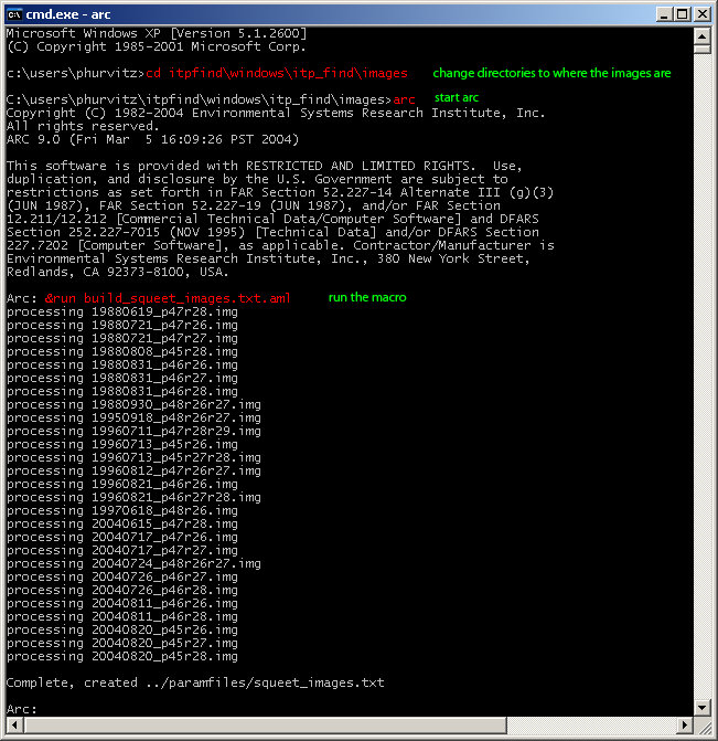
Once the AML is copied into the images directory, start a commands prompt (Start > Run > cmd) and change directories to where the images are located (note: if you hate typing like me, you can do this easily by typing in cd <space> and then dragging the folder from the Windows Explorer to the command prompt).
Start ArcInfo Workstation and then run the macro. This will create the file paramfiles\squeet_images.txt.
System text is grey, commands to enter are in red, the reason for the commands are in green.
return to top
Getting start point locations
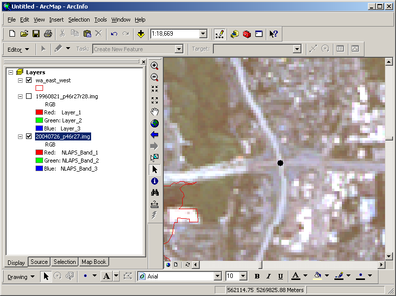
Once you have created the paramfiles\squeet_images.txt file you will need to alter the start point coordinates. This can be done fairly painlessly (that is, no typing!) with ArcMap. You need to decide which images will be used for reference (2004) and which will be input (these are the ones to be rectified, 1988 and 1996). Think in terms of pairs: each image to be rectified needs a reference image.
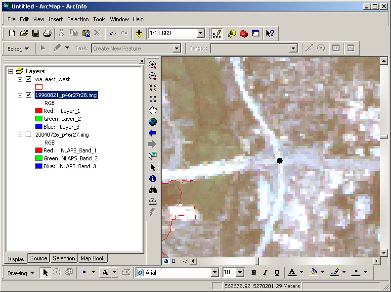
In this example I am using 19960821_p46r27r28.img as the input image and 20040726_p46r27.img as the reference.
- Load the images into ArcMap.
- Find a location that you can recognize on both images. In this example the location is the intersection of I-90 and I-405.
- Add a simple graphical point to the map display on the reference image.
- Right-click the point to view its coordinates.
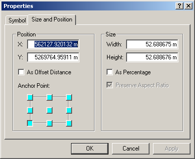
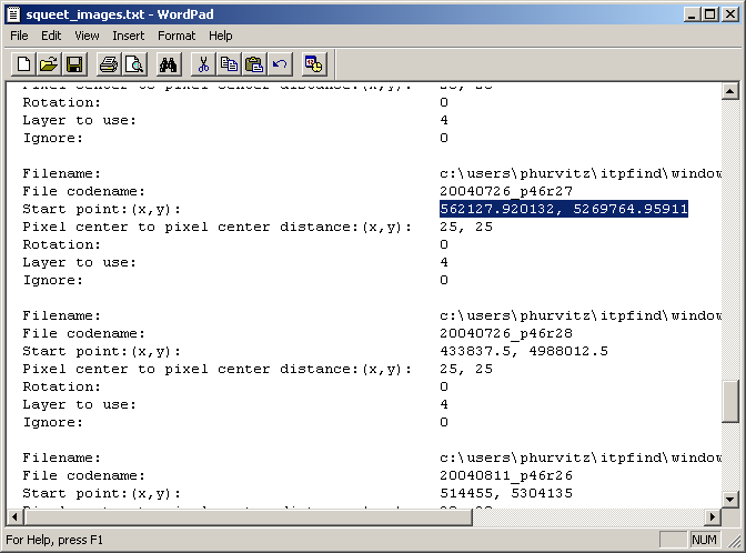
- Copy-and-paste the X and Y values from this dialog into the paramfiles\squeet_images.txt file for this image:
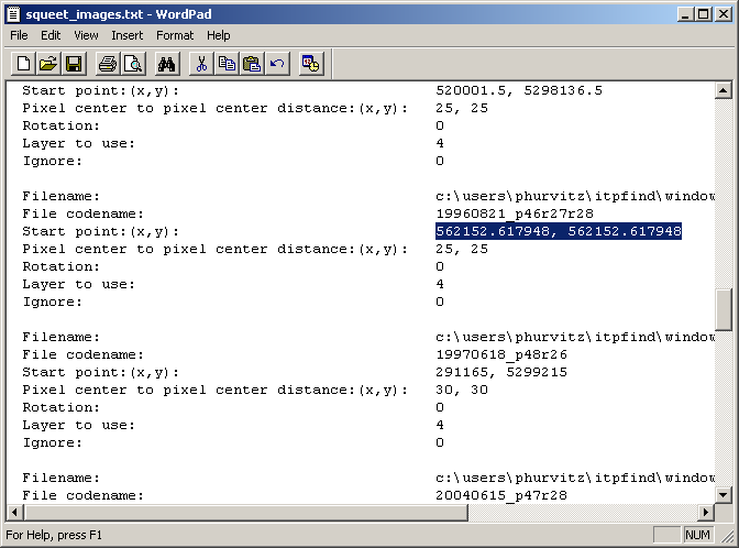
- Do the same for the input image:

- For maximum efficiency you should probably do all the point gathering at one time. This will also make sure you have obtained coordinates for all images. The AML automatically sets start point values to 0 for all images, so updates are necessary for any images you want to process.
return to top
Running ITPFIND
- Start IDL.
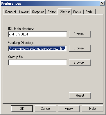
- File > Preferences to set the path to the Working Directory (the root directory of the itp_find installation) so IDL can find the necessary files.
- Start the IDPFIND application by entering @find in the IDL command line at the bottom of the application.
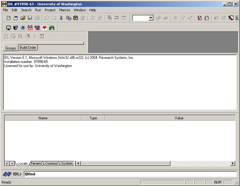
- This will start the application. If your setup files have been created correctly you will see a list of available image and parameter files. If there are no values in these lists, fix your setup files (theremay also be informative text in the IDL log).
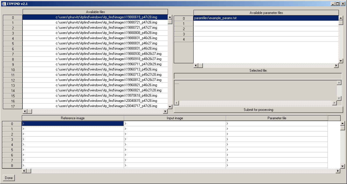
- Click the reference image name in available files for the reference image and then click in the 0 row for Reference image.
- Click the input image name in available files for the input image and then click in the 0 row for Input image.
- Click the parameter file name in available parameter files for the reference image and then click in the 0 row for Parameter file.
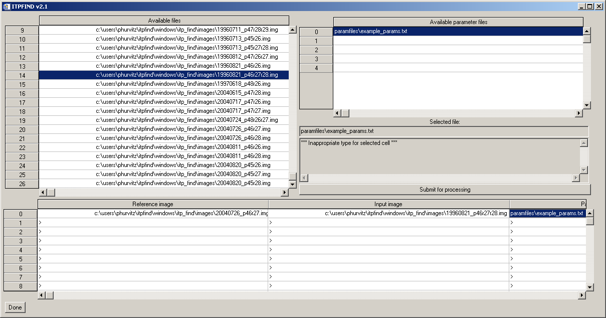
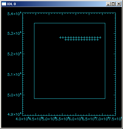
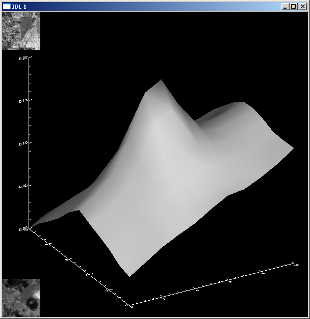
- Click the Submit for processing button. This will open two graphical windows that will display the ITP grid and the comparison surface for each ITP. The IDL application will also scroll a series of command logs. If there are errors anywhere in your setup files, the process will not start or finish, but the errors in the IDL log should be helpful for figuring out what you have done wrong.
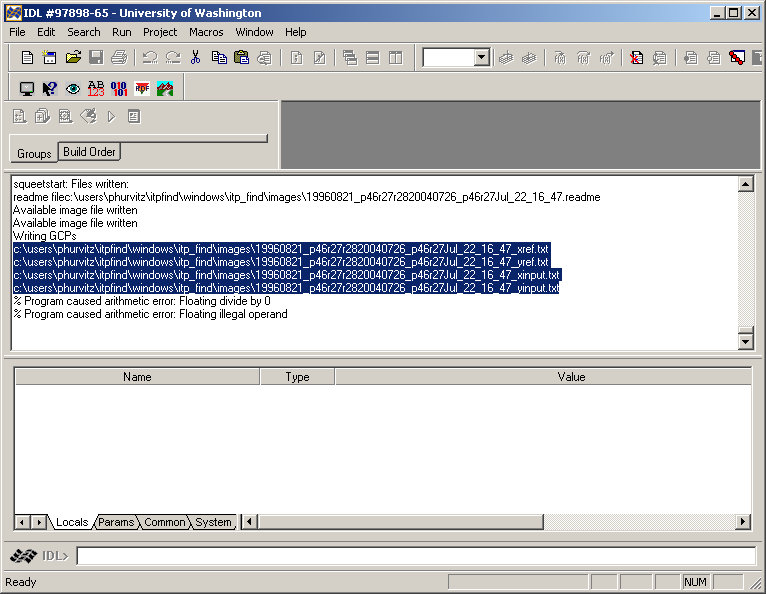
- The process will complete after a few minutes. The IDL log will show what files have been created. These will be used in Imagine to perform the image rectification.
return to top
Running georectification in Imagine
- Start Imagine and load the image that will be rectified in the viewer.
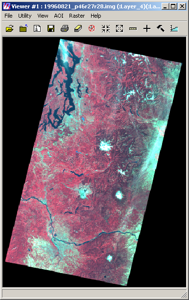
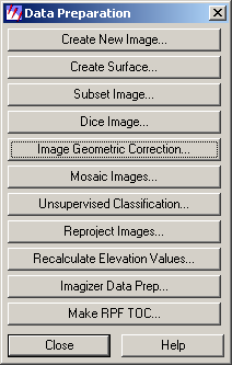
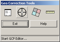
- Start Data Prep > Image Geometric Correction.
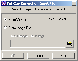
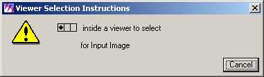
- Select the image to correct in the viewer (click Select Viewer) and then click inside the viewer.
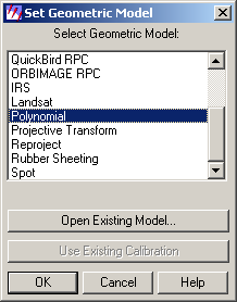
- Set the Geometric Model as Polynomial. Most of the image corrections will be simple XY translations but if there is any warping this should take care of it.
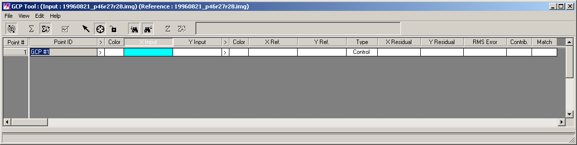
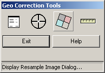
- The Geo Correction tools will start. Click the GCP (Ground control points) Editor tool.
The table will be empty.
- Right-click the X Input column and select Import.
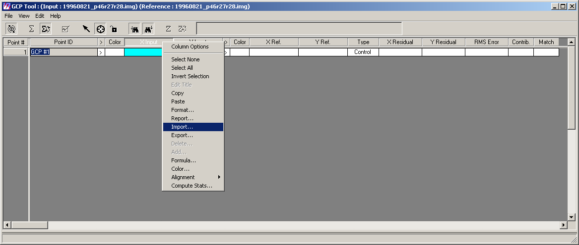
The easiest way to select the file to import is to copy the *xinput filename from the IDL command log ...
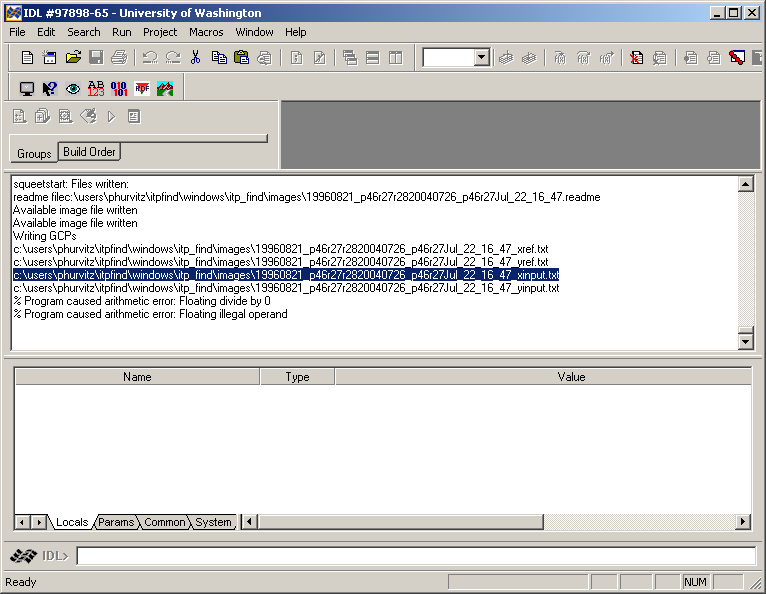
and paste this in the Import Column Data dialog.
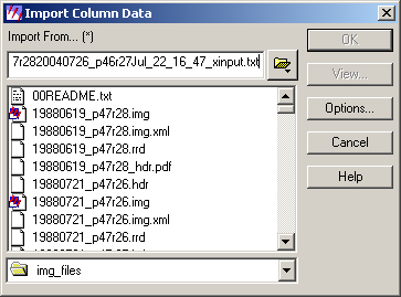
Now you will see that the column has been filled in with a number of entries.
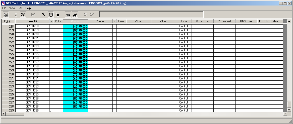
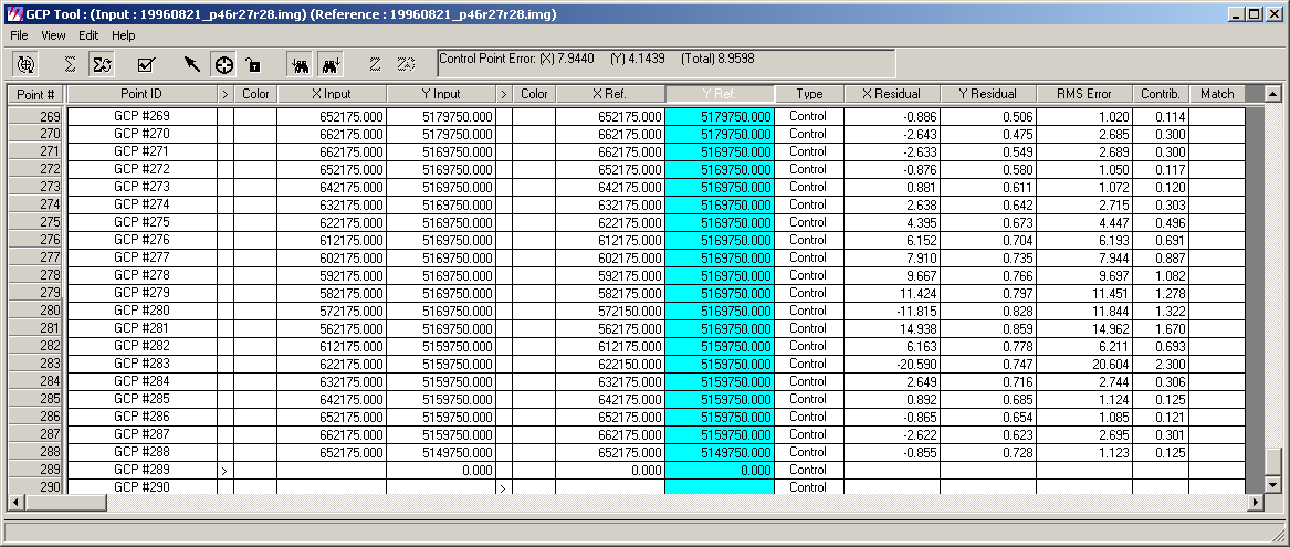
- Do this for each column. Note that after all columns have been imported there are values for residuals in X and Y as well as RMS error for each GCP.
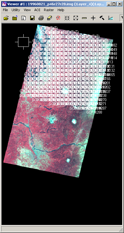
After all the columns have been imported, note the viewer show all the GCPs.
- Click the Display Resample Image Dialog tool.
- Enter the name of the output rectified image. In this example I have created a new directory to hold rectified images and given them the same names as the input images.
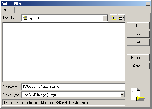
Set the image's properties (e.g., cell size) if necessary.
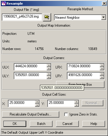
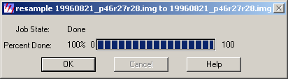
- Click OK and the process will proceed.
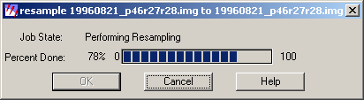
The process will be complete when the Job State shows Done.
- How did you do? Check your work by either:
- Loading two images into an Imagine viewer and using the Utilities
> Swipe or Blend tools. Check the original
and new image against the reference image.
- Loading the images into an ArcMap document and using the Swipe
tool, layer transparencies, or turning layers on and off.
return to top
© 2005 Phil Hurvitz